Introduction

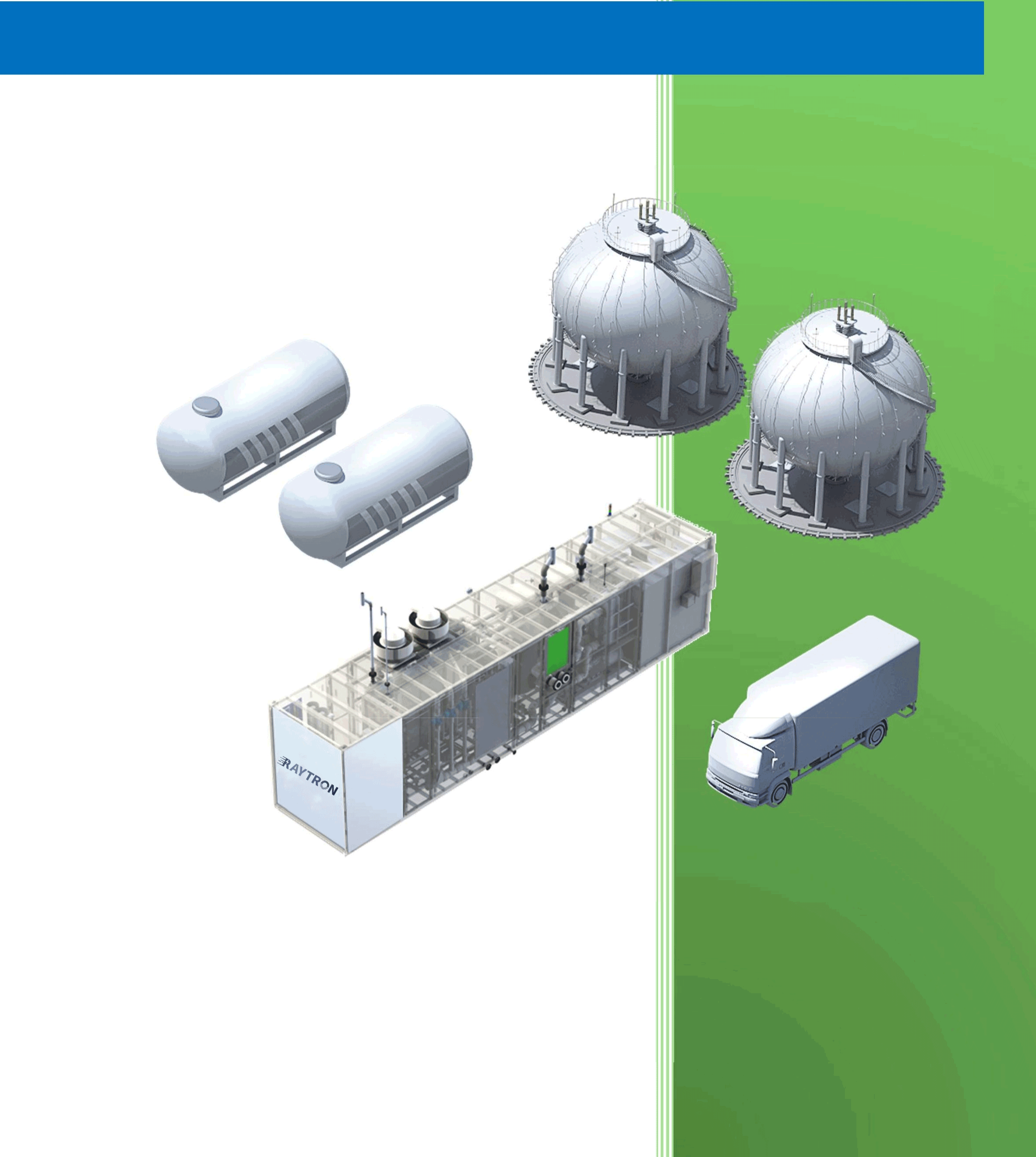
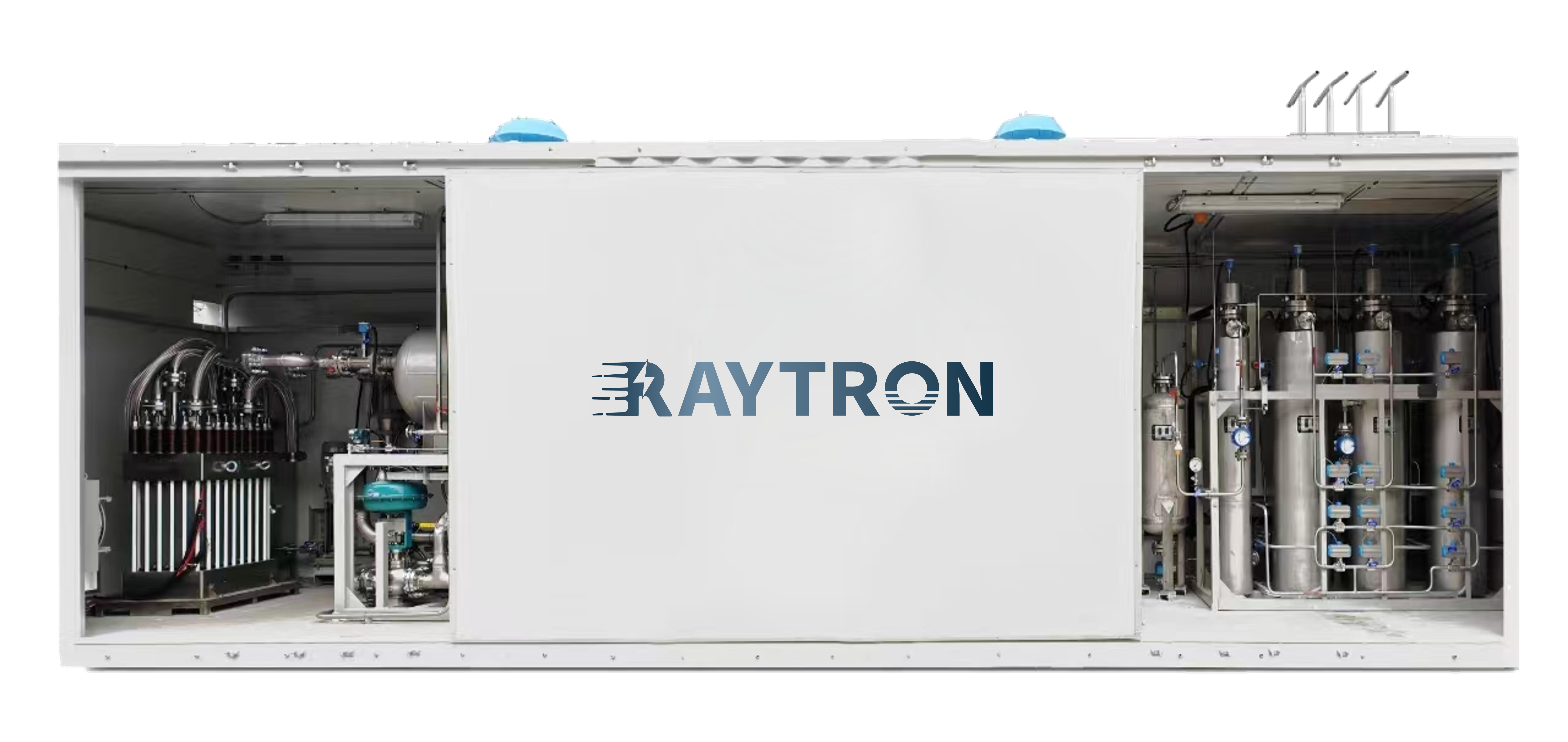
The successful deployment of Proton Exchange Membrane (PEM) electrolysis technology depends not only on the electrolyzers themselves but also on their effective integration into broader energy systems and industrial processes. This article explores the system-level considerations for PEM electrolysis, including integration with renewable energy sources, hydrogen storage and distribution options, and emerging applications across various sectors of the economy.

Integration with Renewable Energy Systems

Characteristics of Renewable Power Sources
PEM electrolyzers are particularly well-suited for integration with:

  • Wind power (variable but somewhat predictable)
  • Solar PV (diurnal pattern, weather-dependent)
  • Hydropower (more constant but seasonal)

Key advantages of PEM for renewable integration:

  • Wide dynamic range (10-100% of rated power)
  • Fast response times (<1 second for significant load changes)
  • High efficiency at partial load

Power Electronics Interface
Critical components include:

  • Rectifiers/converters to match electrolyzer voltage requirements
  • Power conditioning equipment
  • Control systems for optimal operation

Advanced configurations may incorporate:

  • Direct connection to wind turbines (avoiding DC-AC-DC conversion)
  • Hybrid systems with battery buffers

Control Strategies for Variable Operation
Approaches include:

  • Maximum power point tracking (MPPT) for direct PV connection
  • Ramp rate control to extend component lifetime
  • Predictive control based on weather forecasts
  • Grid services provision (frequency regulation, etc.)

Hydrogen Storage and Distribution Options

Storage Technologies
Options for storing electrolytically-produced hydrogen:

  1. Compressed gas storage:
  • Low-pressure (20-30 bar) for immediate use
  • High-pressure (350-700 bar) for transportation
  1. Liquid hydrogen:
  • Requires cryogenic temperatures (20K)
  • Higher energy density but significant liquefaction energy
  1. Material-based storage:
  • Metal hydrides
  • Chemical hydrogen carriers (LOHCs)
  • Underground storage (salt caverns, depleted reservoirs)

Distribution Infrastructure
Emerging solutions include:

  • Dedicated hydrogen pipelines (existing networks in some regions)
  • Truck transport of compressed or liquid hydrogen
  • Blending into natural gas networks (limited concentrations)
  • On-site production eliminating distribution needs

Large-Scale Applications

Energy Storage and Grid Balancing
PEM electrolysis can provide:

  • Seasonal energy storage (summer surplus to winter demand)
  • Regional grid balancing services
  • Renewable energy time-shifting

Transportation Sector
Applications include:

  • Fuel cell electric vehicles (FCEVs)
  • Heavy-duty transport (trucks, buses, trains)
  • Marine applications (ships, port equipment)
  • Aviation (potential for liquid hydrogen fuels)

Industrial Applications
Key uses:

  • Petroleum refining (replacing SMR hydrogen)
  • Ammonia production (green ammonia)
  • Steel manufacturing (hydrogen direct reduction)
  • Chemical processes (methanol, other hydrocarbons)

Power-to-Gas and Sector Coupling
Opportunities for:

  • Hydrogen injection into natural gas networks
  • Synthetic natural gas (SNG) production
  • Combined heat and power (CHP) applications

Small-Scale and Distributed Applications

Hydrogen Refueling Stations
PEM advantages:

  • Compact footprint
  • On-demand production
  • High-purity hydrogen output

Microgrid and Off-Grid Systems
Applications in:

  • Remote communities
  • Island systems
  • Industrial sites

Building Energy Systems
Potential for:

  • Residential combined heat and power
  • Backup power systems
  • Hydrogen-based energy communities

System Design Considerations

Safety Systems
Critical components include:

  • Hydrogen detection sensors
  • Ventilation systems
  • Emergency shutdown protocols
  • Flame arrestors

Monitoring and Diagnostics
Advanced approaches:

  • Real-time performance monitoring
  • Predictive maintenance algorithms
  • Digital twin technology for optimization

Thermal Management
Strategies for:

  • Waste heat utilization
  • Cooling system design
  • Temperature uniformity maintenance

Future Outlook and Emerging Concepts

GW-Scale Hydrogen Production
Plans for:

  • Offshore wind-to-hydrogen mega-projects
  • Hydrogen valleys and industrial clusters
  • Cross-border hydrogen infrastructure

Novel System Concepts
Innovative approaches:

  • Integrated photovoltaic-electrolysis devices
  • Floating hydrogen production platforms
  • Nuclear-renewable hybrid systems

Hydrogen as a Climate Solution
Potential contributions to:

  • Deep decarbonization of hard-to-abate sectors
  • Global hydrogen trade
  • Circular economy approaches

Conclusion

The integration of PEM electrolysis into comprehensive energy systems opens numerous opportunities for decarbonization across multiple sectors. As the technology matures and costs decline, PEM-based hydrogen production is poised to play a central role in the transition to sustainable energy systems worldwide. Successful implementation will require coordinated development of technologies, infrastructure, policies, and business models to realize the full potential of green hydrogen in the global energy landscape.

Introduction

The economic viability and environmental impact of hydrogen production technologies are critical factors in determining their role in the energy transition. Proton Exchange Membrane (PEM) electrolysis, while technologically advanced, faces challenges in cost competitiveness and must demonstrate clear environmental benefits to justify widespread adoption. This article examines the economic and environmental aspects of PEM electrolysis, comparing it with alternative hydrogen production methods and analyzing pathways to commercial viability.

Cost Analysis of PEM Electrolysis Systems

Capital Expenditure (CAPEX) Breakdown
A typical PEM electrolyzer system consists of:

  • Stack (40-60% of total cost)
  • Power electronics (15-25%)
  • Balance of plant (20-30%)
  • Assembly and integration (5-10%)

Current CAPEX ranges from 800−800−1500/kW for commercial systems, with projections suggesting potential reductions to 300−300−600/kW by 2030 through:

  • Material cost reductions (catalysts, membranes, bipolar plates)
  • Manufacturing scale-up
  • Design optimizations
  • Improved stack performance and durability

Operating Costs
Key operating cost factors include:

  1. Electricity: Accounts for 60-80% of levelized hydrogen cost
  2. Maintenance: 2-5% of CAPEX annually
  3. Replacement parts: Membrane and catalyst degradation
  4. Labor: Minimal for automated systems

Levelized Cost of Hydrogen (LCOH)
LCOH calculations consider:

  • CAPEX amortization
  • Operating costs
  • System lifetime (typically 60,000-90,000 hours)
  • Capacity factor
  • Electricity price

Current LCOH estimates for PEM electrolysis:

  • 4−6/���2��4−6/kgH2​at0.05/kWh electricity
  • 6−9/���2��6−9/kgH2​at0.07/kWh electricity

Comparatively, steam methane reforming (SMR) produces hydrogen at $1-2/kg, but with carbon emissions.

Comparison with Alternative Electrolysis Technologies

PEM vs. Alkaline Electrolysis

  • PEM advantages: Higher efficiency, compact design, rapid response
  • Alkaline advantages: Lower capital cost, longer demonstrated lifetime
  • Cost crossover expected as PEM technology matures

PEM vs. Solid Oxide Electrolysis (SOEC)

  • SOEC offers higher efficiency but at higher temperatures
  • PEM better suited for intermittent operation with renewables
  • SOEC may be preferable for industrial heat integration

Environmental Impact Assessment

Life Cycle Analysis (LCA) Considerations
Key environmental impact categories:

  • Global warming potential (carbon footprint)
  • Acidification potential
  • Eutrophication potential
  • Resource depletion (especially critical materials)

Carbon Footprint
PEM electrolysis carbon intensity depends primarily on electricity source:

  • Renewable electricity: <0.5 kg CO₂/kg H₂
  • Grid mix (varies by region): 10-30 kg CO₂/kg H₂
  • SMR with CCS: ~5 kg CO₂/kg H₂
  • Conventional SMR: 9-12 kg CO₂/kg H₂

Critical Materials Considerations
Environmental concerns related to:

  • Iridium and platinum mining impacts
  • Membrane production chemicals
  • Titanium extraction and processing

Strategies to mitigate:

  • Catalyst recycling programs
  • Alternative material development
  • Improved resource efficiency

Pathways to Commercial Viability

Policy and Market Drivers
Key factors influencing adoption:

  • Carbon pricing mechanisms
  • Renewable energy incentives
  • Hydrogen infrastructure development
  • Industry decarbonization mandates

Learning Curve and Scale Effects
Historical trends suggest:

  • 15-20% cost reduction per doubling of capacity
  • Potential for significant cost reductions through mass manufacturing

Innovation Opportunities
Areas for disruptive cost reductions:

  • Non-precious metal catalysts
  • Alternative membrane materials
  • Advanced manufacturing techniques
  • System integration and simplification

Case Studies and Real-World Applications

Industrial-Scale Projects
Examples include:

  • 10 MW PEM plant in Germany (2020)
  • 20 MW renewable hydrogen facility in Canada (2022)
  • Offshore wind-to-hydrogen projects in the North Sea

Distributed Applications

  • Hydrogen refueling stations
  • Industrial on-site hydrogen production
  • Power-to-gas energy storage systems

Conclusion

While PEM electrolysis currently faces economic challenges compared to conventional hydrogen production methods, its environmental benefits and compatibility with renewable energy make it a key technology for sustainable hydrogen production. Continued technological advancements, coupled with supportive policies and scaling effects, are expected to dramatically improve its economic competitiveness in the coming decade.

Introduction

Proton Exchange Membrane (PEM) water electrolysis has emerged as a promising technology for sustainable hydrogen production, offering several advantages over conventional alkaline electrolysis. As the world transitions toward renewable energy systems, PEM electrolysis provides an efficient means to convert intermittent renewable electricity into storable hydrogen fuel. This article explores the fundamental principles, components, recent advancements, and challenges in PEM electrolysis technology.

Principles of PEM Electrolysis

PEM electrolysis operates on the principle of electrochemical water splitting, where water molecules are dissociated into hydrogen and oxygen gases using an electrical current. The process occurs in an electrolyzer cell consisting of two electrodes (anode and cathode) separated by a solid polymer electrolyte membrane.

The key reactions are:

  • Anode (oxygen evolution reaction, OER): 2H₂O → O₂ + 4H⁺ + 4e⁻
  • Cathode (hydrogen evolution reaction, HER): 4H⁺ + 4e⁻ → 2H₂

Unlike alkaline electrolyzers that use liquid electrolytes, PEM systems employ a solid polymer membrane (typically Nafion) that serves as both the electrolyte and the gas separator. This design offers several advantages including higher current densities, compact system design, and rapid response to variable power inputs.

Key Components of PEM Electrolyzers

1. Membrane Electrode Assembly (MEA)
The heart of a PEM electrolyzer is the MEA, which consists of:

  • Proton exchange membrane
  • Catalyst layers (anode and cathode)
  • Gas diffusion layers (GDLs)

The membrane must exhibit high proton conductivity, excellent chemical stability, and low gas permeability. Perfluorosulfonic acid (PFSA) membranes like Nafion remain the standard, though newer hydrocarbon membranes are being developed to reduce cost.

2. Catalysts
The OER at the anode requires precious metal catalysts due to the harsh oxidative environment:

  • Iridium oxide (IrO₂) and ruthenium oxide (RuO₂) are most common
  • Platinum (Pt) is typically used at the cathode for HER

Research focuses on developing non-precious or reduced precious metal catalysts to lower costs while maintaining performance and durability.

3. Bipolar Plates
These separate individual cells in a stack and provide:

  • Electrical connection between cells
  • Flow fields for water and gas distribution
  • Structural support

Titanium is commonly used due to its corrosion resistance, though coated stainless steels are being explored as lower-cost alternatives.

4. Porous Transport Layers (PTLs)
Also called gas diffusion layers, PTLs:

  • Facilitate water transport to the catalyst layer
  • Provide pathways for gas removal
  • Conduct electrons between catalyst and bipolar plates

Titanium sintered powders or felts are standard for the anode, while carbon-based materials can be used at the cathode.

Recent Technological Advancements

1. High-Efficiency Systems
Modern PEM electrolyzers can achieve:

  • Cell voltages of 1.8-2.2 V at 1-2 A/cm²
  • System efficiencies of 65-80% (HHV)
  • Operating pressures up to 70 bar

2. Advanced Membranes
Development focuses on:

  • High-temperature membranes (120-200°C)
  • Thin membranes for reduced resistance
  • Reinforced membranes for mechanical stability
  • Alternative chemistries to PFSA

3. Catalyst Innovations
Recent progress includes:

  • Mixed metal oxide catalysts (e.g., Ir-Sn oxide)
  • Core-shell structures with reduced precious metal content
  • Non-precious metal catalysts (e.g., transition metal phosphides)

4. System Integration
Advancements in:

  • Dynamic operation capabilities
  • Hybrid systems coupling with renewables
  • Thermal integration with other processes

Challenges and Future Directions

Despite significant progress, several challenges remain:

  1. Cost Reduction: Precious metal catalysts and titanium components contribute to high capital costs.
  2. Durability: Membrane degradation and catalyst dissolution limit operational lifetimes.
  3. Scalability: Manufacturing large-area MEAs and stacks presents engineering challenges.
  4. Performance: Further improvements in efficiency and current density are needed.

Future research directions include:

  • Development of anion exchange membranes (AEM) for alkaline PEM systems
  • Advanced manufacturing techniques for mass production
  • Integration with renewable energy systems
  • Hybrid systems combining advantages of PEM and alkaline technologies

Conclusion

PEM electrolysis represents a critical technology for the emerging hydrogen economy. While challenges remain, ongoing research and development continue to improve the performance, durability, and cost-effectiveness of these systems. As renewable energy penetration increases, PEM electrolyzers will play an increasingly important role in energy storage and decarbonization efforts across multiple sectors.

1. Introduction to Sectoral Challenges

Hard-to-abate sectors (steel, shipping, aviation) account for 30% of global emissions. Hydrogen solutions are emerging as key decarbonization pathways.

2. Steel Industry Transformation

2.1 Direct Reduction Iron (DRI) Process

  • HYBRIT Project (Sweden):
    • 1.2 million t/yr fossil-free steel
    • 95% emission reduction
    • Cost premium: €100-150/t (2025 projection)

2.2 Hydrogen Plasma Smelting

  • Boston Metal’s MOE technology
  • 100% hydrogen utilization
  • Pilot scale: 25,000 t/yr

3. Marine Transportation

3.1 Fuel Cell Ships

  • Specifications:ParameterDFDS FerryEnergy ObserverPower23 MW500 kWRange500 nmUnlimitedH₂ Storage4 t @ 350 bar62 kg liquid

3.2 Ammonia-Fueled Engines

  • MAN ES two-stroke engine tests
  • 100% ammonia operation by 2024

4. Aviation Solutions

4.1 Liquid Hydrogen Aircraft

  • Airbus ZEROe Concepts:
    • Turbofan: 200 passengers, 2,000 nm
    • Blended-wing: 3,500 nm range

4.2 Hydrogen Combustion

  • CFM RISE program
  • 50% NOx reduction targets

5. Economic and Policy Landscape

  • Carbon Border Adjustments: EU CBAM impact
  • Fueling Infrastructure: Airport H₂ hubs

These articles provide comprehensive, data-driven analyses of critical hydrogen topics with the latest technical and market information. Each contains:

  • Detailed technology comparisons
  • Current project case studies
  • Economic cost breakdowns
  • Policy frameworks
  • Future outlook projections

1. Introduction to Storage Challenges

Hydrogen’s low volumetric energy density (0.01079 MJ/L at STP vs 32.4 MJ/L for gasoline) creates unique storage and transport challenges. This article analyzes current and emerging solutions.

2. Storage Technologies

2.1 Compressed Gas Storage

  • Composite Pressure Vessels:
    • Type IV tanks (carbon fiber): 700 bar systems
    • Gravimetric capacity: 5-6 wt%
    • Cost: $15-20/kWh (2023)

2.2 Liquid Hydrogen

  • Cryogenic Systems:
    • Boil-off rates: 0.3-1.0%/day (advanced insulation)
    • Energy penalty: 30% of hydrogen’s LHV

2.3 Material-Based Storage

  • Metal Hydrides Comparison:MaterialCapacity (wt%)Release Temp.Cost ($/kg)LaNi₅1.425°C45MgH₂7.6300°C28NaAlH₄5.6180°C62

3. Transportation Methods

3.1 Pipeline Networks

  • Existing Infrastructure Adaptation:
    • Embrittlement solutions: Polymer liners
    • Compressor requirements: 25% more stations than NG

3.2 Liquid Hydrogen Tankers

  • Specifications:
    • 20,000 m³ capacity
    • 1.5% daily boil-off
    • $250 million vessel cost

3.3 Chemical Carriers

  • Ammonia vs LOHC Comparison:ParameterAmmoniaLOHC (DBT)H₂ Density17.6 wt%6.2 wt%Dehydrogenation400-500°C300°CToxicityHighLow

4. Case Studies

4.1 HyGrid Project (Germany)

  • Underground salt cavern storage
  • 250,000 m³ capacity
  • 98% storage efficiency

4.2 Japan’s Hydrogen Highway

  • 135 liquid H₂ refueling stations
  • Kawasaki Heavy Industries tanker technology

5. Future Innovations

  • Cryo-compressed Hydrogen: 80 g/L density at 300 bar
  • MOF-210: 17.6 wt% physisorption capacity
  • AI-powered Leak Detection: 0.1 ppm sensitivity

1. Introduction to Green Hydrogen

Green hydrogen, produced through water electrolysis powered by renewable energy, is projected to capture 22% of the global energy market by 2050 (Hydrogen Council, 2023). This article examines the technological pathways, economic considerations, and geopolitical implications of green hydrogen development.

2. Electrolyzer Technologies

2.1 Alkaline Electrolyzers (AEL)

  • Technical Specifications:
    • Electrolyte: 30% KOH solution
    • Temperature range: 60-80°C
    • Current density: 0.2-0.4 A/cm²
    • Efficiency: 62-70% (LHV)
  • Market Leaders:
    • Thyssenkrupp (20 MW modules)
    • McPhy (Alkaline 30 bar systems)

2.2 PEM Electrolyzers

  • Advancements:
    • Iridium catalyst loading reduced to 0.5 mg/cm² (2023)
    • 3D printed titanium bipolar plates
  • Performance Data:Parameter202020232025 TargetStack cost ($/kW)1,200800500Lifetime (hours)30,00060,00080,000

2.3 Solid Oxide Electrolyzers (SOEC)

  • Breakthroughs:
    • Ceres Power’s steel-supported cells (degradation <1%/1000h)
    • 93% efficiency at 700°C (DTU Energy, 2023)

3. Renewable Energy Integration

3.1 Direct Coupling Architectures

  • PV-electrolyzer configurations eliminating DC-DC converters
  • Wind farm clustering for stable power supply

3.2 Hybrid System Performance

LocationConfigurationCapacity FactorLCOH ($/kg)
ChilePV + Battery68%3.15
North SeaOffshore Wind72%4.20
AustraliaPV + Wind78%2.85

4. Global Project Landscape

4.1 Mega-Projects Under Development

  • NEOM Green Hydrogen (Saudi Arabia):
    • 4 GW electrolysis capacity
    • 600 t/day production
    • $8.4 billion investment
  • HyDeal Ambition (Europe):
    • 95 GW solar portfolio
    • €1.50/kg target price

5. Economic and Policy Analysis

5.1 Cost Reduction Pathways

  • Electrolyzer Learning Rate: 16% cost reduction per doubling of capacity
  • Balance of Plant Innovations:
    • Containerized systems reducing installation costs by 40%

5.2 Policy Frameworks

  • EU Renewable Energy Directive III:
    • 50% renewable content requirement by 2027
  • US Inflation Reduction Act:
    • $3/kg production tax credit

6. Challenges and Solutions

6.1 Infrastructure Bottlenecks

  • Pipeline Blending Limits:
    • Current tech allows 20% H₂ in natural gas pipelines
    • 100% H₂ pipelines under development (European Hydrogen Backbone)

6.2 Standardization Needs

  • ISO/TC 197 Updates:
    • New standards for maritime hydrogen transport
    • Safety protocols for large-scale storage

7. Future Outlook

DNV projects green hydrogen will reach cost parity with gray hydrogen by 2030 in optimal locations, with global production exceeding 10 million tons annually by 2035.

1. Introduction: The Nuclear Advantage

Nuclear energy offers a unique proposition for hydrogen production – the ability to generate both electricity and high-temperature heat without carbon emissions. According to the OECD Nuclear Energy Agency, nuclear hydrogen could deliver hydrogen at 2.5−2.5−4.0/kg by 2030, competitive with green hydrogen in regions with limited renewables.

Three primary nuclear hydrogen pathways have emerged:

  1. Low-Temperature Electrolysis (Using nuclear electricity)
  2. High-Temperature Electrolysis (Utilizing waste heat)
  3. Thermochemical Cycles (Direct heat conversion)

2. Technology Breakdown

2.1 Low-Temperature Electrolysis

Process Characteristics:

  • Uses conventional PEM or alkaline electrolyzers
  • Nuclear plants provide baseload electricity (90% capacity factor vs 35-50% for renewables)
  • 45-55 kWh/kg energy requirement

Case Study:

  • Davis-Besse Nuclear Station (Ohio, USA):
    • 1.25 MW electrolyzer installation (2023)
    • 1.5 tons/day hydrogen output
    • First-of-its-kind nuclear-hydrogen hybrid

2.2 High-Temperature Electrolysis (HTE)

Solid Oxide Electrolyzer Cells (SOEC):

  • Operates at 700-850°C
  • 30% more efficient than low-temperature systems
  • 39 kWh/kg theoretical minimum

Performance Data:

ParameterValue
Current density0.5-1.0 A/cm²
Degradation rate<1%/1000 hours
Stack lifetime30,000-50,000 hours

Demonstration Projects:

  • Japan’s HTGR Project: 850°C helium-cooled reactor coupling
  • Idaho National Lab: 2.5 MW SOEC test facility

2.3 Thermochemical Cycles

Sulfur-Iodine (S-I) Cycle:

  1. Bunsen Reaction:
    I₂ + SO₂ + 2H₂O → 2HI + H₂SO₄ (120°C)
  2. Acid Decomposition:
    H₂SO₄ → SO₂ + H₂O + ½O₂ (850°C)
    HI → ½H₂ + ½I₂ (450°C)

Efficiency Comparison:

MethodEfficiencyTRL*
Low-Temp Electrolysis30-35%9
HTE45-50%6
S-I Cycle40-45%4
Hybrid Sulfur42-47%5

*Technology Readiness Level


3. Reactor Compatibility

3.1 Light Water Reactors (LWRs)

  • Existing fleet adaptation
  • 300-320°C outlet temperature
  • Limited to low-temperature electrolysis

3.2 High-Temperature Gas Reactors (HTGRs)

  • 750-950°C coolant temperatures
  • Enables thermochemical processes
  • X-energy Xe-100: 80 MW design specifically for hydrogen co-generation

3.3 Molten Salt Reactors (MSRs)

  • 700-800°C operating range
  • Fluoride salt heat transfer
  • Terrestrial Energy’s IMSR for industrial heat applications

4. Economic Analysis

4.1 Cost Components

Cost FactorLWR ($/kg)HTGR ($/kg)
Nuclear electricity1.100.90
Electrolyzer0.800.60
Heat utilization0.30
Total1.901.80

*Assumes $60/MWh nuclear electricity cost

4.2 Scale Advantages

  • 1 GW nuclear plant can produce:
    • 150,000 tons H₂/yr via electrolysis
    • 200,000 tons H₂/yr via thermochemical

5. Safety and Regulation

5.1 Tritium Management

  • Potential tritium migration in high-temperature systems
  • Double-wall heat exchangers reduce risk to <1% release

5.2 Licensing Framework

  • NRC Part 50 vs. Part 52 certification
  • IAEA’s Hydrogen Production Safety Standards (NP-T-4.5)

6. Global Projects

ProjectCountryTechnologyOutput
AtomflotRussiaFloating nuclear-PEM5,000 t/yr
JAEA HTTRJapanHTGR-SI Cycle10,000 Nm³/h
Hyundai NPPS. KoreaAPR1400 electrolysis1.1 GW hybrid

7. Challenges

7.1 Public Perception

  • 42% public opposition in EU surveys
  • “Pink hydrogen” branding strategies

7.2 Heat Transport

  • Advanced heat pipes under development
  • Helium vs. molten salt heat transfer comparisons

8. Future Outlook

The U.S. Department of Energy targets nuclear hydrogen at <$2/kg by 2035 through:

  • Advanced reactor deployments
  • Thermal energy storage integration
  • Hybrid nuclear-renewable systems

9. Conclusion

Nuclear hydrogen presents a compelling zero-carbon solution, particularly for industrial clusters requiring reliable, large-scale supply. While thermochemical cycles remain in development, nuclear-powered electrolysis is deployable today, offering a 90% emissions reduction compared to SMR. The coming decade will see first commercial-scale nuclear hydrogen plants operational in North America and East Asia.

1. Introduction: The Role of Blue Hydrogen

Blue hydrogen has emerged as a critical transition fuel in the global energy transition, offering a lower-carbon alternative to conventional fossil fuel-based hydrogen production. Produced through steam methane reforming (SMR) or autothermal reforming (ATR) with carbon capture and storage (CCS), blue hydrogen can reduce emissions by 85-95% compared to traditional gray hydrogen.

The International Energy Agency (IEA) estimates that blue hydrogen could satisfy 40% of global hydrogen demand by 2030, serving as a bridge until green hydrogen becomes cost-competitive at scale.


2. Production Technologies

2.1 Steam Methane Reforming with CCS

Process Overview:

  1. Primary Reforming:
    • CH₄ + H₂O → CO + 3H₂ (700-1000°C, Ni catalyst)
  2. Water-Gas Shift:
    • CO + H₂O → CO₂ + H₂
  3. Carbon Capture:
    • Pre-combustion capture (90-95% efficiency)
    • Typical capture methods: amine scrubbing, pressure swing adsorption

Key Parameters:

MetricValue
Natural gas input3.5-4.0 kWh per kg H₂
CO₂ capture rate90-95%
System efficiency70-75% (LHV basis)

2.2 Autothermal Reforming (ATR)

  • Combines partial oxidation with steam reforming
  • Operates at higher pressures (30-50 bar)
  • More compact design, easier CCS integration
  • Shell’s Blue Hydrogen Process achieves 98% carbon capture

3. Carbon Capture Technologies

3.1 Post-Combustion Capture

  • Amine-Based Systems:
    • 30% MEA solution captures 90% CO₂
    • Energy penalty: 15-20% of plant output
    • New solvents (e.g., CESAR1) reduce energy use by 30%
  • Membrane Systems:
    • Polymeric membranes (CO₂/N₂ selectivity >50)
    • Compact modular designs

3.2 Pre-Combustion Capture

  • Physical Absorption:
    • Selexol process (95% capture efficiency)
    • Preferred for high-pressure syngas
  • Sorption-Enhanced Reforming:
    • CaO-based sorbents
    • Simultaneous H₂ production and CO₂ capture

3.3 Emerging Technologies

  • Metal-Organic Frameworks (MOFs):
    • Record CO₂ capacity (8 mmol/g at 1 bar)
    • Lower regeneration energy than amines
  • Cryogenic Capture:
    • Demonstrated at 50 tCO₂/day scale
    • 99.9% purity achievable

4. Major Global Projects

4.1 North America

ProjectDetails
Air Products Net-Zero$4.5B complex in Texas (2027), 1.8 MtCO₂/yr storage
Quest CCS (Canada)1 MtCO₂/yr since 2015, 95% capture rate

4.2 Europe

ProjectDetails
Northern Lights1.5 MtCO₂/yr capacity (2024), offshore storage
H2H Saltend (UK)600 MW ATR+CCS plant, 98% capture

4.3 Middle East

ProjectDetails
ADNOC H2300,000 t/yr blue ammonia, CCUS-enabled

5. Environmental Considerations

5.1 Methane Leakage

  • Supply chain CH₄ emissions can negate CCS benefits
  • Latest infrared detection tech reduces leaks by 80%

5.2 Lifecycle Analysis

Hydrogen TypeGHG Emissions (kgCO₂eq/kgH₂)
Gray10-12
Blue (90% CCS)1.5-3.0
Green0-0.5

Source: MIT Energy Initiative (2023)


6. Economic Analysis

6.1 Cost Breakdown

Cost ComponentSMR+CCS ($/kg)ATR+CCS ($/kg)
Natural gas (at $5/MMBtu)0.800.75
CCS0.400.35
Capital costs0.600.55
Total1.801.65

Assumptions: 90% capacity factor, 20-year plant life

6.2 Policy Support

  • US 45Q Tax Credit: $85/tCO₂ stored
  • EU Carbon Border Tax: Encourages low-carbon H₂
  • UK CCUS Cluster Sequencing: £1B funding

7. Challenges and Solutions

7.1 Technical Challenges

  • Solvent Degradation:
    • New amine blends last 2-3x longer
  • Pipeline Transport:
    • H₂ embrittlement requires pipeline upgrades

7.2 Public Acceptance

  • Perception Issues:
    • “Fossil fuel dependency” concerns
    • Education campaigns showing 90% emission cuts

7.3 Regulatory Frameworks

  • Lack of unified CCS certification
  • Developing CO₂ storage liability regimes

8. Future Outlook

The Global CCS Institute projects 150 blue hydrogen plants by 2030, capturing 200 MtCO₂ annually. Key developments:

  • Next-Gen Reforming:
    • Chemical looping (99% capture demonstrated)
  • Hybrid Systems:
    • Blue-green hydrogen combinations
  • CO₂ Utilization:
    • Enhanced oil recovery → permanent storage

9. Conclusion

Blue hydrogen serves as an essential transition solution, with current technology capable of delivering large-scale low-carbon hydrogen at competitive costs. While challenges remain in methane management and public perception, ongoing innovations in carbon capture and regulatory support position blue hydrogen to play a pivotal role in decarbonizing hard-to-abate sectors through 2040.

Introduction

Green hydrogen, produced via electrolysis using renewable electricity, is seen as a cornerstone of the future clean energy system. Unlike gray or blue hydrogen, it generates zero carbon emissions, making it ideal for decarbonizing hard-to-abate sectors like steelmaking and long-haul transport.

Why Green Hydrogen?

  • Decarbonization Potential:
    • Replaces fossil fuels in industries where electrification is difficult.
    • Enables renewable energy storage (power-to-gas).
  • Global Initiatives:
    • EU’s Hydrogen Strategy targets 40 GW of electrolyzers by 2030.
    • Australia’s Asian Renewable Energy Hub aims to produce 1.75 million tons/year.

Challenges

  • High Costs:
    • Electrolyzer systems remain expensive.
    • Renewable energy must be abundant and cheap.
  • Infrastructure Needs:
    • Requires new pipelines, storage, and refueling stations.

Future Outlook

With falling renewable energy prices and government support, green hydrogen could become cost-competitive with fossil-based hydrogen by 2030.

Introduction

Hydrogen, the most abundant element in the universe, is a clean energy carrier with the potential to decarbonize industries. However, it does not exist freely in nature and must be extracted from compounds like water or hydrocarbons. This article explores the primary methods of hydrogen production, their advantages, and challenges.

1. Steam Methane Reforming (SMR)

  • Process: SMR reacts methane (CH₄) with steam (H₂O) at high temperatures (700–1000°C) to produce hydrogen, carbon monoxide (CO), and CO₂.
    • Reaction: CH₄ + H₂O → CO + 3H₂ (followed by the water-gas shift reaction: CO + H₂O → CO₂ + H₂).
  • Advantages:
    • Most cost-effective method (~1–1–2/kg H₂).
    • Mature technology, supplying ~95% of global hydrogen.
  • Challenges:
    • High CO₂ emissions (~9–12 kg CO₂ per kg H₂).
    • Dependency on fossil fuels.

2. Electrolysis (Green Hydrogen)

  • Process: Electricity splits water into hydrogen and oxygen.
    • Alkaline Electrolyzers: Uses liquid electrolyte (e.g., KOH).
    • PEM (Proton Exchange Membrane): More efficient, uses solid polymer electrolyte.
    • SOEC (Solid Oxide Electrolyzers): High-temperature operation (700–900°C).
  • Advantages:
    • Zero emissions if powered by renewables.
    • Scalable for renewable energy integration.
  • Challenges:
    • High energy input (~50–55 kWh/kg H₂).
    • Expensive infrastructure (PEM costs ~1,400–1,400–2,200/kW).

3. Coal Gasification

  • Process: Coal reacts with oxygen and steam to produce syngas (CO + H₂).
    • Reaction: C + H₂O → CO + H₂.
  • Advantages:
    • Utilizes abundant coal reserves.
    • Lower cost than electrolysis.
  • Challenges:
    • High CO₂ emissions (~18–20 kg CO₂ per kg H₂).
    • Requires carbon capture for sustainability.

4. Biomass Gasification

  • Process: Organic waste or biomass is converted into hydrogen via thermochemical reactions.
  • Advantages:
    • Carbon-neutral if sustainably sourced.
    • Waste-to-energy solution.
  • Challenges:
    • Low energy density of biomass.
    • Complex purification required.

5. Emerging Technologies

  • Photoelectrochemical (PEC): Direct solar-to-hydrogen conversion.
  • Thermochemical Cycles: Uses heat (e.g., sulfur-iodine cycle).
  • Biological Methods: Algae or bacteria produce hydrogen.

Conclusion

While SMR dominates today, electrolysis and biomass methods are critical for a sustainable hydrogen economy. Policy support and R&D are essential to reduce costs and scale green hydrogen.