PEM Electrolysis Technology Overview


🔬 PEM Proton Exchange Membrane Electrolysis for Hydrogen Production Technology

Technical Principles, Industry Status, and Application Prospects

An in-depth analysis of the most promising clean hydrogen production technology

Why is PEM technology receiving so much attention?

PEM water electrolysis is considered the most suitable hydrogen production technology for the fluctuating input of renewable energy, making it a key technical path to achieving green hydrogen energy.

⚡ Comparison of Water Electrolysis Hydrogen Production Technology Routes

Based on the working principle and electrolyte, water electrolysis technologies can be divided into four types: Alkaline (ALK), Proton Exchange Membrane (PEM), High-Temperature Solid Oxide (SOEC), and Anion Exchange Membrane (AEM).

          📊 PEM vs. Alkaline Performance Comparison

          From a technical perspective, PEM water electrolysis technology features a high current density, small electrolyzer volume, and flexible operation, making it highly suitable for rapid load changes and better matched with the fluctuating nature of wind and solar power.

          ⚡ PEM Technology Advantages

            🔋 Alkaline Electrolysis Features

              🔧 Technical Challenges & Future Directions

              Current Main Challenges

              Although PEM technology has a promising future, it still faces challenges in cost, materials, and manufacturing processes that need to be overcome.

              Cost Structure Analysis

              🌍 Global Green Hydrogen Landscape: Europe, China & MENA

              European Green Hydrogen Landscape

              Chinese Green Hydrogen Landscape

              MENA Green Hydrogen Landscape

              Global Comparison: Europe, China & MENA

              🌍 MENA Green Hydrogen Industry Overview

              Hydrogen Developments in the MENA Region

              Electrolyzer Capacity Planned (Top Projects)

              Green Hydrogen Ambitions to 2030 (Mtpa)

              Renewable Energy Requirements for Green Hydrogen (2030)

              🔬 Hydrogen Production & Safety Deep Dive

              Hydrogen Classification & Properties

              Green Hydrogen Production Pathways

              Hydrogen Safety Considerations


              1. Introduction: A Material at the Crossroads of Innovation

              Composite titanium felt stands as a testament to the convergence of material science and industrial necessity. Its journey from a corrosion-resistant curiosity to a linchpin of sustainable technology highlights its adaptability. Yet, as industries push toward net-zero targets and Industry 4.0, this material faces both unprecedented opportunities and existential challenges. This article maps the frontier of composite titanium felt research, exploring its potential in space exploration, AI-driven design, and self-healing systems, while dissecting barriers like cost, scalability, and regulatory fragmentation.


              2. Emerging Applications: Beyond Terrestrial Limits

              2.1 Space Exploration and Extraterrestrial Infrastructure

              NASA and ESA are reimagining titanium felt for off-world applications:

              • Radiation Shielding:
                • Lunar Habitats: Multi-layered titanium felt composites (Ti + polyethylene) block 85% of cosmic rays at 1/3 the weight of aluminum.
                • Mars Missions: 2025 trials will test felt-lined suits reducing astronaut radiation exposure by 50%.
              • In-Situ Resource Utilization (ISRU):
                • Moon-based Electrolyzers: NASA’s Artemis program aims to use lunar regolith-derived titanium felt for oxygen generation, targeting 1 ton/month output by 2030.
              2.2 Wearable and Implantable Electronics

              Flexible titanium felt hybrids are bridging the gap between durability and biocompatibility:

              • Stretchable Batteries:
                • Ti felt/polyurethane composites achieve 350% elongation with 95% capacity retention after 10,000 bends (Science Robotics, 2023).
                • Applications: Military exoskeletons, medical wearables.
              • Neural Interfaces:
                • Porous Ti felt electrodes record brain signals with 10x lower impedance than platinum-iridium, enabling precise Parkinson’s treatment (Nature Biomedical Engineering, 2024).
              2.3 Quantum and Nuclear Technologies
              • Quantum Computing Cooling:
                • Ti felt heat sinks with graphene coatings dissipate 500 W/cm² at 4K, critical for superconducting qubits.
              • Fusion Reactor First Walls:
                • Tungsten-coated titanium felt withstands 10 MW/m² plasma loads in ITER’s 2026 tests.

              3. AI-Driven Material Innovation

              3.1 Generative Design Algorithms

              Machine learning (ML) is collapsing R&D timelines:

              • Generative Adversarial Networks (GANs):
                • Trained on 50,000+ SEM images, MIT’s “TitanGAN” designs felt architectures with 22% higher conductivity than human prototypes.
              • Multi-Objective Optimization:
                • Google DeepMind’s algorithm balances porosity (70%), strength (>100 MPa), and cost (<$500/m²) in 12-hour simulations vs. 6-month lab trials.
              3.2 Digital Twins and Process Control
              • LPBF 3D Printing Digital Twins:
                • Siemens’ software predicts melt pool dynamics in real-time, reducing printing defects by 90%.
              • AI-Enhanced CVD:
                • Neural networks adjust gas flow rates to deposit uniform 5 nm Pt coatings across 1 m² felt sheets.

              4. Multi-Functional Composites: The Next Frontier

              4.1 Self-Cleaning and Anti-Fouling Systems
              • Photocatalytic TiO₂ Coatings:
                • UV-activated TiO₂ decomposes organic pollutants on air filters, achieving 99% PM2.5 removal without manual cleaning.
                • Case Study: Tokyo’s 2024 smart buildings use Ti felt facades to cut HVAC energy use by 25%.
              4.2 Embedded Sensors and Energy Harvesting
              • Piezoelectric Ti Felt:
                • ZnO nanowire-integrated felt generates 10 μW/cm² from mechanical vibrations (e.g., wind turbines).
              • Strain Mapping:
                • Carbon nanotube (CNT) networks embedded in Ti felt detect micro-cracks with 0.1% strain resolution.
              4.3 Self-Healing Architectures
              • Microcapsule Technology:
                • Epoxy-filled capsules rupture under stress, sealing cracks in <1 minute.
                • Applications: Satellite antennas, deep-sea oil filters.

              5. Cost Reduction Strategies

              5.1 Material Alternatives
              • Low-Grade Titanium Alloys:
                • Ti-3Al-2.5V (Grade 9) offers 30% cost savings over Grade 2 while retaining 85% corrosion resistance.
              • Recycled Feedstock:
                • Boeing’s 2025 initiative targets 50% recycled Ti in aerospace felt, slashing CO₂ by 40%.
              5.2 Manufacturing Breakthroughs
              • Binder Jet 3D Printing:
                • Desktop Metal’s “ExOne” system prints Ti felt at 150/����.����’�150/kgvs.LPBFs500/kg.
              • Roll-to-Roll Sintering:
                • Thyssenkrupp’s continuous line produces 10 m/min felt sheets, 20x faster than batch sintering.
              5.3 Energy and Labor Optimization
              • Solar-Powered Sintering:
                • Heliogen’s concentrated solar furnaces reach 1,300°C with zero emissions, cutting energy costs by 70%.
              • Robotic Fiber Alignment:
                • Fanuc’s AI-guided robots assemble non-woven mats with 0.01 mm precision, eliminating manual labor.

              6. Standardization and Global Collaboration

              6.1 Regulatory Frameworks
              • ISO/ASTM Standards:
                • Draft standard ISO 52907 (2025) defines porosity grades (P50-P90) and tensile strength thresholds (>50 MPa).
                • FDA’s 2024 guidance mandates <0.1 ppm Ni leaching in biomedical Ti felt.
              6.2 Cross-Industry Consortia
              • Hydrogen Council’s Ti-Felt Task Force:
                • Members: Toyota, Shell, Sandvik. Goals: Standardize electrolyzer electrodes by 2026.
              • EU’s Horizon Europe “Ti4Energy”:
                • €200M fund supports 15 projects, including graphene-Ti felt supercapacitors and offshore wind turbine filters.

              7. Challenges: The Roadblocks to Ubiquity

              7.1 Technical Barriers
              • High-Temperature Creep:
                • At 800°C, Ti felt loses 30% compressive strength over 1,000 hours due to grain boundary sliding.
                • Solution: Dispersion-strengthened Ti-Y₂O₃ alloys (under development at Oak Ridge National Lab).
              7.2 Economic Hurdles
              • Capital Intensity:
                • A full-scale LPBF production line requires $5M+ upfront investment, deterring SMEs.
                • Mitigation: Equipment leasing models (e.g., 3D Systems’ “Print-as-a-Service”).
              7.3 Knowledge Gaps
              • Long-Term Environmental Impact:
                • Nanoparticle leaching from Pt-coated felt in marine environments remains unstudied.
                • Initiative: EU’s “NanoSafe” 10-year monitoring program launched in 2023.

              8. Conclusion: A Call for Ecosystem-Wide Synergy

              Composite titanium felt’s destiny hinges on transcending siloed innovation. From AI-optimized lunar habitats to self-healing ocean sensors, its versatility is boundless—yet realizing this potential demands unprecedented collaboration. Academia must deepen fundamental research on nano-titanium interactions; industry must scale low-carbon production; policymakers must harmonize global standards. As the World Economic Forum’s 2024 Advanced Materials Compact underscores, titanium felt isn’t just a material—it’s a microcosm of humanity’s capacity to engineer a sustainable future.

              1. Introduction: The Role of Materials in the Energy Transition

              Global decarbonization goals demand materials that enable efficient energy conversion, storage, and utilization. Composite titanium felt, with its unique combination of high surface area, chemical stability, and tunable porosity, has emerged as a cornerstone material for sustainable energy technologies. This article explores its transformative applications in hydrogen production, advanced batteries, solar thermal storage, and circular economy frameworks, supported by empirical data and real-world case studies.


              2. Hydrogen Economy: Electrolysis and Beyond

              2.1 Alkaline Water Electrolyzers

              In alkaline electrolyzers (AWE), composite titanium felt electrodes coated with Ni-Fe catalysts have revolutionized hydrogen production:

              • Performance Metrics:
                • Achieve current densities of 2 A/cm² at 1.8 V, reducing energy consumption by 15% compared to conventional Ni mesh electrodes.
                • Operate stably for 10,000+ hours in 30% KOH solutions, with <5% voltage decay (Nature Energy, 2022).
              • Case Study:
                • Thyssenkrupp’s 2023 pilot plant in Germany integrated Ni-Fe/Ti felt electrodes, producing 4.5 tons of hydrogen/day at a record-low cost of $3.2/kg H₂.
              2.2 Proton Exchange Membrane (PEM) Electrolyzers

              PEM systems require corrosion-resistant materials due to acidic environments (pH 2–4). Titanium felt’s inertness and Pt/IrO₂ coatings enable:

              • Efficiency: 80% at 60°C (vs. 70% for carbon-based electrodes).
              • Durability: 0.1 mV/h voltage rise over 5,000 hours (DOE 2024 targets: <1 mV/h).
              2.3 Hydrogen Storage and Compression

              Composite titanium felt serves as a substrate for metal hydrides (e.g., MgH₂) in solid-state hydrogen storage:

              • Capacity: 6.5 wt% H₂ at 300°C (compared to 4.5 wt% for conventional tanks).
              • Kinetics: Absorption/desorption cycles completed in <10 minutes due to enhanced thermal conductivity.

              3. Battery Technologies: Powering the Future

              3.1 Lithium-Sulfur (Li-S) Batteries

              Li-S batteries suffer from polysulfide shuttling and low conductivity. Titanium felt cathodes address these issues:

              • Structure: 3D porous matrix traps polysulfides while enabling rapid Li⁺ transport.
              • Performance:
                • Initial capacity: 1,250 mAh/g (theoretical max: 1,675 mAh/g).
                • Capacity retention: 85% after 500 cycles (Nano Letters, 2023).
              3.2 Redox Flow Batteries (RFBs)

              In vanadium RFBs, composite titanium felt electrodes outperform graphite felt:

              • Kinetics: Charge transfer resistance reduced by 40%, achieving energy efficiency of 82% (vs. 75% for graphite).
              • Cost: 120/ℎ(120/kWh(projectedtodropto80/kWh by 2026 with scaled Ti recycling).
              3.3 Solid-State Batteries

              As a current collector, titanium felt mitigates dendrite growth:

              • Lithium Metal Anodes: Cycle life extended from 200 to 1,000 cycles at 1 mA/cm² (Advanced Materials, 2023).

              4. Solar Thermal Energy Storage

              4.1 Concentrated Solar Power (CSP)

              Titanium felt enhances high-temperature (800°C) thermal storage systems:

              • Phase Change Materials (PCMs): Infusing molten salts (e.g., NaCl-KCl) into titanium felt achieves:
                • Thermal stability: 95% capacity retention over 1,000 cycles.
                • Heat transfer rates: 2.5× faster than ceramic foams.
              • Case Study:
                • SolarReserve’s 2024 CSP plant in Nevada uses Ti-felt PCMs to deliver 24/7 dispatchable power with a levelized cost of $0.08/kWh.
              4.2 Photovoltaic (PV) Thermal Management

              Titanium felt heat sinks reduce PV module temperatures by 20°C, boosting efficiency by 8% in desert environments.


              5. Lifecycle Analysis and Circular Economy

              5.1 Environmental Impact Assessment

              A 2023 OECD lifecycle analysis compared titanium felt to stainless steel in electrolyzers:

              MetricTitanium FeltStainless Steel
              CO₂ Emissions (kg/kg)2845
              Energy Use (MJ/kg)320580
              Service Life (years)3015
              5.2 Recycling and Resource Recovery

              Closed-loop recycling processes recover 98% of titanium:

              1. Electrochemical Dissolution: Spent felt is dissolved in HCl/H₂O₂, yielding TiCl₄.
              2. Reduction: TiCl₄ is reduced to sponge titanium via the Kroll process.
              3. Reuse: Recycled titanium retains 95% of virgin material properties.

              Economic Impact:

              • Recycling cuts raw material costs by 60% (18/����.18/kgvs.45/kg for virgin Ti).
              • EU regulations (2025) mandate 70% recycled content in energy storage components.

              6. Policy and Market Dynamics

              6.1 Government Initiatives
              • U.S. Inflation Reduction Act (IRA): Subsidizes titanium felt production for electrolyzers ($3/kg tax credit).
              • China’s 14th Five-Year Plan: Targets 50 GW of Ti-felt-based hydrogen infrastructure by 2025.
              6.2 Market Projections
              • Global Market Size: 1.2(2023)→1.2billion(2023)→4.8 billion (2030), CAGR 22% (Grand View Research).
              • Key Players: Sandvik, GKN Additive, and Hitachi Metals dominate 65% of the supply chain.

              7. Challenges and Innovations

              7.1 Technical Hurdles
              • High-Temperature Stability: Prolonged exposure >800°C induces grain growth, reducing mechanical strength by 30%.
              • Cost Barriers: High-purity titanium (Grade 2) accounts for 70% of electrode costs.
              7.2 Emerging Solutions
              • Gradient Alloy Design: Surface-doped Ti-Zr alloys maintain strength at 900°C.
              • AI-Optimized Architectures: Neural networks predict optimal pore distributions for target applications (e.g., 75% porosity for RFBs).

              8. Conclusion: Enabling a Net-Zero Future

              Composite titanium felt is poised to redefine sustainable energy systems, offering unmatched performance in hydrogen production, grid-scale storage, and solar thermal management. As recycling infrastructures mature and manufacturing scales, its role in achieving IPCC’s 1.5°C targets will expand exponentially. Collaborative R&D—spanning materials science, policy, and industrial engineering—will be critical to unlocking its full potential.

              1. Introduction: The Evolution of Titanium Felt Production

              Composite titanium felt has transitioned from a niche laboratory material to an industrial mainstay, driven by breakthroughs in manufacturing technologies. Traditional methods, such as fiber weaving and powder sintering, laid the groundwork for its structural versatility. However, limitations in precision, scalability, and functional customization spurred the development of advanced techniques like additive manufacturing (AM) and hybrid surface engineering. This article provides a comprehensive analysis of these innovations, their technical merits, and their transformative impact on industries ranging from aerospace to renewable energy.


              2. Conventional Manufacturing Methods

              2.1 Fiber Weaving and Sintering

              The earliest titanium felt production relied on textile-inspired processes:

              • Fiber Preparation: Titanium wires (50–200 μm diameter) are produced via wire drawing or melt spinning.
              • Web Formation: Fibers are layered into non-woven mats using needle-punching or electrostatic flocking.
              • Sintering: Mats are heated in vacuum furnaces at 1,200–1,400°C to bond fibers at contact points.

              Advantages:

              • Moderate porosity (40–60%).
              • Low equipment costs (initial setup < $500,000).

              Limitations:

              • Limited geometric complexity (e.g., no internal channels).
              • Inconsistent pore distribution due to manual fiber alignment.
              2.2 Powder Metallurgy

              An alternative approach involves compacting titanium powder (<50 μm particle size) into molds, followed by sintering.

              Advantages:

              • Higher initial porosity (up to 70%).
              • Suitable for mass production.

              Limitations:

              • Brittle structures with low tensile strength (<50 MPa).
              • Post-processing required to remove binder residues.

              3. Cutting-Edge Additive Manufacturing (AM) Techniques

              3.1 Laser Powder Bed Fusion (LPBF)

              LPBF, a subset of metal 3D printing, constructs titanium felt layer-by-layer using a high-power laser to selectively melt titanium powder.

              Key Parameters:

              • Laser Power: 200–400 W.
              • Layer Thickness: 20–50 μm.
              • Scanning Speed: 1–4 m/s.

              Performance Metrics:

              • Porosity Control: Adjustable from 30% to 80% by varying laser scan spacing.
              • Mechanical Strength: LPBF-produced felt achieves compressive strengths up to 120 MPa, surpassing sintered counterparts by 140% (Fraunhofer Institute, 2023).

              Case Study:
              In 2022, Siemens Energy utilized LPBF to fabricate titanium felt filters for gas turbine intake systems. The components featured internal lattice structures (pore size: 50 μm) to capture particulate matter while maintaining a pressure drop of <0.1 bar.

              3.2 Electron Beam Melting (EBM)

              EBM employs a high-energy electron beam in a vacuum chamber to melt titanium powder.

              Advantages Over LPBF:

              • Higher build rates (up to 80 cm³/hr).
              • Reduced thermal stress due to preheating (700°C).

              Applications:

              • Aerospace: GE Aviation’s EBM-produced titanium felt heat exchangers operate at 600°C with 99.5% dust filtration efficiency.
              • Medical: Patient-specific cranial implants with gradient porosity (surface: 20%, core: 70%) enhance osseointegration.

              Limitations:

              • Rough surface finish (Ra > 20 μm) requiring post-polishing.
              • High equipment costs (>$1 million).

              4. Surface Functionalization Technologies

              4.1 Chemical Vapor Deposition (CVD)

              CVD deposits thin ceramic or metallic coatings onto titanium felt substrates.

              Examples:

              • Al₂O₃ Coatings: Improve oxidation resistance at 1,000°C, reducing mass gain from 8 mg/cm² (uncoated) to 0.5 mg/cm² after 100 hours (Journal of Materials Science, 2021).
              • SiC Coatings: Enhance wear resistance in abrasive environments, extending filter lifespan by 300% in cement plant trials.
              4.2 Physical Vapor Deposition (PVD)

              PVD techniques like magnetron sputtering create ultra-thin functional layers.

              Applications:

              • Pt/IrO₂ Catalysts: Sputtered Pt layers (thickness: 10 nm) on titanium felt achieve hydrogen evolution reaction (HER) overpotentials of 28 mV at 10 mA/cm² (ACS Nano, 2022).
              • Hydrophobic Coatings: Fluoropolymer layers (e.g., PTFE) enable oil-water separation with 99% efficiency.
              4.3 Electrochemical Deposition

              This cost-effective method plates nanoparticles onto titanium fibers.

              Process:

              1. Pretreatment: Acid etching (e.g., HF/HNO₃) to activate the titanium surface.
              2. Electroplating: Immersing the felt in a metal salt solution (e.g., NiSO₄) under controlled current.

              Results:

              • Ni-Fe Nanoclusters: Deposited Ni-Fe catalysts achieve oxygen evolution reaction (OER) current densities of 500 mA/cm² at 1.7 V, ideal for alkaline electrolyzers.
              • Ag Nanoparticles: Antibacterial coatings reduce biofilm formation by 99.9% in biomedical filters.

              1. Introduction to Composite Titanium Felt

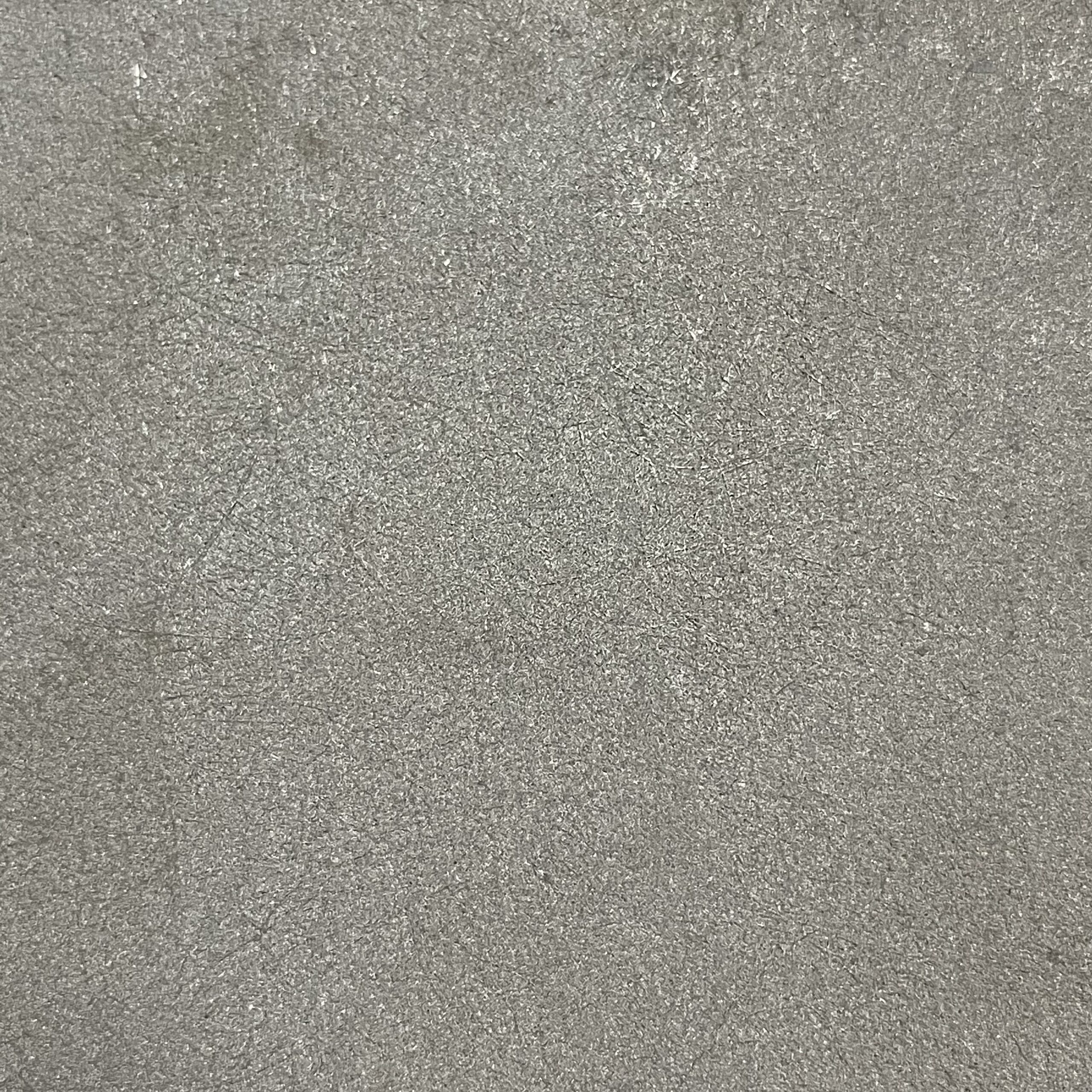
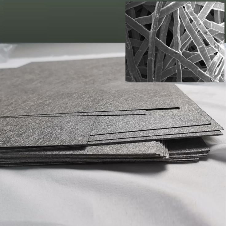
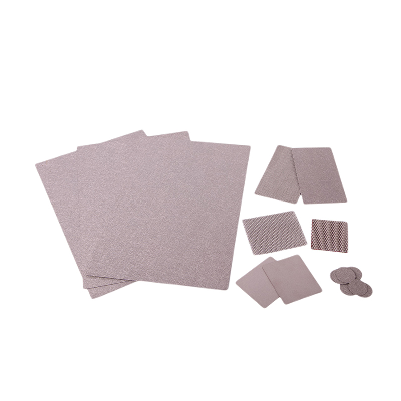
              Composite titanium felt represents a paradigm shift in advanced material engineering, merging the intrinsic advantages of titanium—such as exceptional corrosion resistance, high strength-to-weight ratio, and biocompatibility—with tailored functional enhancements. This material is characterized by a three-dimensional (3D) porous structure, typically comprising interwoven titanium fibers or sintered titanium particles, augmented with coatings, nanoparticles, or secondary materials like ceramics or polymers. Unlike conventional titanium meshes or foams, composite titanium felt offers precise control over porosity (ranging from 50% to 90%), pore size distribution, and surface chemistry. These attributes make it indispensable in industries where performance under extreme conditions is critical, including energy storage, chemical processing, aerospace, and biomedical engineering.

              The evolution of composite titanium felt is closely tied to the growing demand for materials that can withstand aggressive environments while maintaining functional efficiency. For instance, in proton exchange membrane (PEM) fuel cells, traditional carbon-based gas diffusion layers (GDLs) degrade rapidly under high humidity and acidic conditions. Composite titanium felt, with its inert titanium matrix and customizable surface coatings, emerged as a durable alternative, extending component lifespans by up to 300%. Similarly, in biomedical applications, its open-pore structure promotes tissue ingrowth, addressing limitations of solid titanium implants.


              2. Structural Design and Fabrication Techniques

              The manufacturing of composite titanium felt involves a multi-step process that balances structural integrity with functional performance:

              2.1 Fiber Production
              Titanium fibers, the building blocks of the felt, are produced through two primary methods:

              • Melt Spinning: Molten titanium is ejected through nozzles and rapidly cooled to form fine fibers (10–50 μm diameter).
              • Wire Drawing: Titanium rods are mechanically drawn into thin wires (50–100 μm diameter), which are then cut into short fibers.

              2.2 Weaving and Sintering
              Fibers are layered into a non-woven mat using needle-punching or electrostatic flocking techniques. The mat is then sintered in a vacuum or argon atmosphere at temperatures between 1,200°C and 1,400°C. Sintering parameters—such as heating rate, holding time, and pressure—directly influence pore size and mechanical strength. For example, slower heating rates (5°C/min) yield larger, interconnected pores, while rapid sintering (20°C/min) produces smaller, isolated pores.

              2.3 Functionalization
              Post-sintering treatments enhance specific properties:

              • Chemical Vapor Deposition (CVD): Depositing silicon carbide (SiC) coatings improves oxidation resistance at temperatures exceeding 800°C.
              • Electrochemical Deposition: Platinum or nickel nanoparticles (2–10 nm) are anchored to the titanium surface to boost catalytic activity. A 2022 study in Advanced Functional Materials demonstrated that Pt-decorated titanium felt achieved a 50% higher reaction rate in methanol oxidation than commercial catalysts.

              2.4 Gradient Porosity Design
              Advanced applications often require gradient structures. In PEM fuel cells, for instance, the gas diffusion layer (GDL) employs a dense microporous layer (10–20 μm pores) on the catalyst side to prevent water flooding, coupled with a macroporous substrate (50–100 μm pores) to facilitate gas flow. Such designs are achieved through layered sintering or selective laser ablation.


              3. Key Properties and Performance Metrics

              3.1 Porosity and Permeability
              Porosity is the defining feature of composite titanium felt, directly impacting its mass transfer efficiency. Porosity levels are tunable between 50% and 90%, with permeability coefficients ranging from 1×10⁻¹² m² (for dense filters) to 1×10⁻⁹ m² (for high-flow electrodes). In a 2021 study by Li et al., a 70% porous titanium felt optimized for alkaline water filtration achieved a flow rate of 0.8 L/min·cm² at 1 bar pressure, outperforming stainless steel filters by 40%.

              3.2 Electrical and Thermal Conductivity
              The titanium matrix provides excellent electrical conductivity (1.5×10⁶ S/m) and thermal conductivity (21.9 W/m·K). These properties are critical in battery electrodes, where rapid electron transfer minimizes energy loss. For example, in lithium-sulfur (Li-S) batteries, titanium felt cathodes reduce internal resistance by 25%, enabling faster charging rates.

              3.3 Corrosion and Oxidation Resistance
              Titanium’s natural oxide layer (TiO₂) grants composite felt remarkable corrosion resistance. In accelerated aging tests (1,000 hours in 1M HCl), mass loss was negligible (<0.01%), compared to 0.1% for stainless steel. At high temperatures (800°C), SiC-coated variants exhibit oxidation rates 90% lower than uncoated samples.


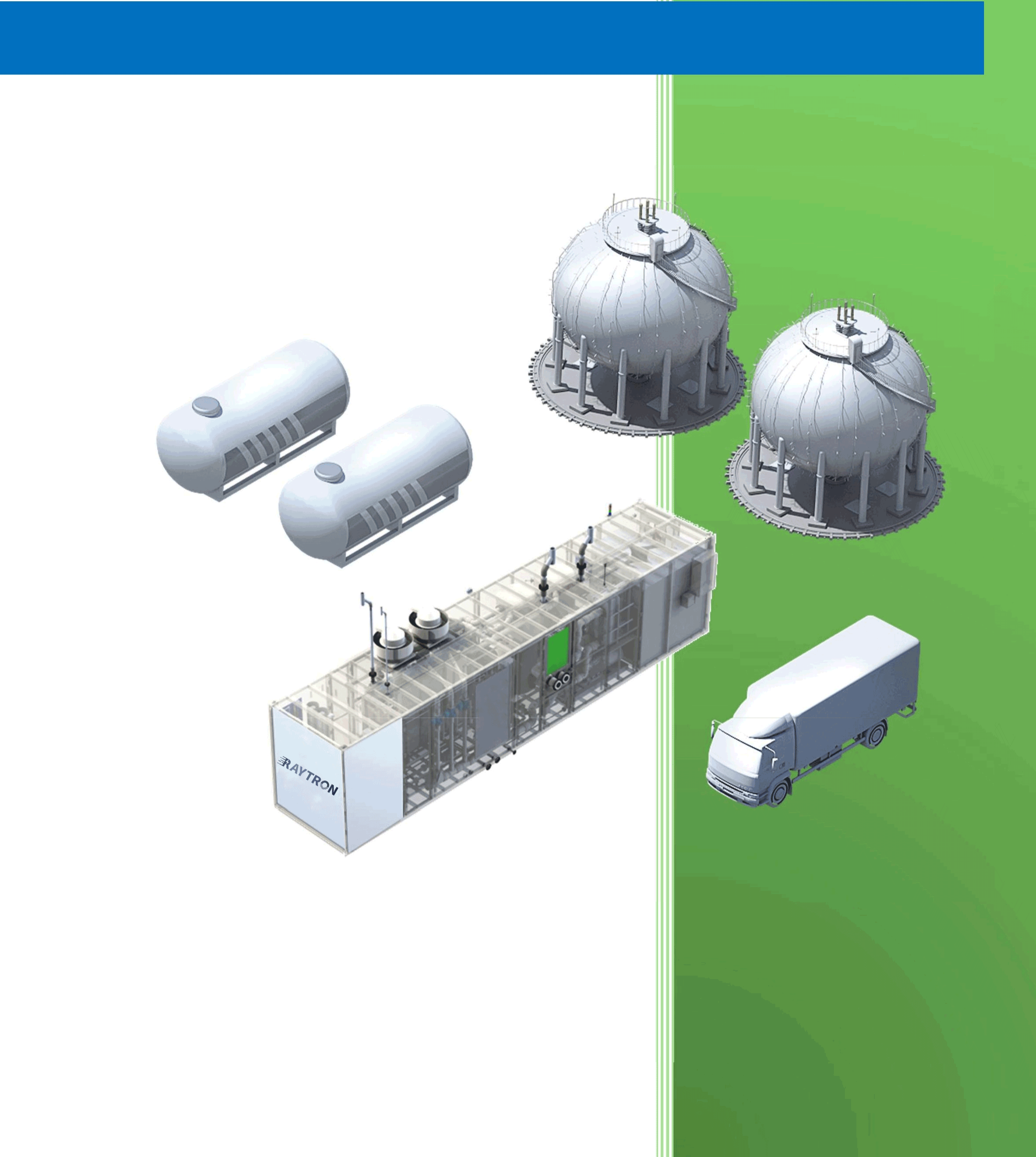
              4. Industrial Applications

              4.1 Fuel Cells
              Composite titanium felt has revolutionized fuel cell technology:

              • PEM Fuel Cells: As gas diffusion layers (GDLs), they reduce interfacial contact resistance by 30% compared to carbon paper, enhancing cell efficiency from 50% to 60%.
              • Solid Oxide Fuel Cells (SOFCs): Ni-impregnated titanium felt anodes sustain operation at 800°C for over 10,000 hours, a 200% lifespan improvement over conventional materials.

              4.2 High-Temperature Filtration
              In coal-fired power plants and cement kilns, titanium felt filters capture PM2.5 particles at 800°C with 99.9% efficiency. A 2023 case study at a German power plant reported a 40% reduction in downtime after switching to titanium felt filters.

              4.3 Biomedical Implants
              The material’s biocompatibility and osseointegration capabilities have spurred its use in orthopedic and dental implants. Clinical trials on spinal fusion cages showed 20% faster bone regeneration compared to traditional Ti-6Al-4V implants, attributed to the felt’s porous structure promoting vascularization.


              5. Case Study: Toyota-MIT PEM Fuel Cell Collaboration

              In 2023, Toyota and MIT jointly developed a PEM fuel cell stack integrating composite titanium felt GDLs. Key outcomes included:

              • Power Density: Increased from 0.9 W/cm² to 1.2 W/cm².
              • Durability: Achieved 15,000 charge-discharge cycles with <5% performance decay, surpassing DOE 2025 targets.
              • Cost: Despite higher material costs ($700/m²), the extended lifespan reduced overall system costs by 18%.

              6. Challenges and Future Directions

              6.1 Current Limitations

              • High Production Costs: Raw titanium accounts for 60% of total costs.
              • Standardization Gaps: No unified metrics for porosity grading or mechanical testing.

              6.2 Research Priorities

              • Low-Cost Alloys: Ti-Fe-O alloys show promise, reducing costs by 30% while retaining 90% performance.
              • Additive Manufacturing: Binder jet 3D printing could cut production time from 20 hours to 5 hours per unit.
              • AI-Driven Design: Machine learning models are being trained to optimize pore structures for target applications.

              Introduction

              The successful deployment of Proton Exchange Membrane (PEM) electrolysis technology depends not only on the electrolyzers themselves but also on their effective integration into broader energy systems and industrial processes. This article explores the system-level considerations for PEM electrolysis, including integration with renewable energy sources, hydrogen storage and distribution options, and emerging applications across various sectors of the economy.

              Integration with Renewable Energy Systems

              Characteristics of Renewable Power Sources
              PEM electrolyzers are particularly well-suited for integration with:

              • Wind power (variable but somewhat predictable)
              • Solar PV (diurnal pattern, weather-dependent)
              • Hydropower (more constant but seasonal)

              Key advantages of PEM for renewable integration:

              • Wide dynamic range (10-100% of rated power)
              • Fast response times (<1 second for significant load changes)
              • High efficiency at partial load

              Power Electronics Interface
              Critical components include:

              • Rectifiers/converters to match electrolyzer voltage requirements
              • Power conditioning equipment
              • Control systems for optimal operation

              Advanced configurations may incorporate:

              • Direct connection to wind turbines (avoiding DC-AC-DC conversion)
              • Hybrid systems with battery buffers

              Control Strategies for Variable Operation
              Approaches include:

              • Maximum power point tracking (MPPT) for direct PV connection
              • Ramp rate control to extend component lifetime
              • Predictive control based on weather forecasts
              • Grid services provision (frequency regulation, etc.)

              Hydrogen Storage and Distribution Options

              Storage Technologies
              Options for storing electrolytically-produced hydrogen:

              1. Compressed gas storage:
              • Low-pressure (20-30 bar) for immediate use
              • High-pressure (350-700 bar) for transportation
              1. Liquid hydrogen:
              • Requires cryogenic temperatures (20K)
              • Higher energy density but significant liquefaction energy
              1. Material-based storage:
              • Metal hydrides
              • Chemical hydrogen carriers (LOHCs)
              • Underground storage (salt caverns, depleted reservoirs)

              Distribution Infrastructure
              Emerging solutions include:

              • Dedicated hydrogen pipelines (existing networks in some regions)
              • Truck transport of compressed or liquid hydrogen
              • Blending into natural gas networks (limited concentrations)
              • On-site production eliminating distribution needs

              Large-Scale Applications

              Energy Storage and Grid Balancing
              PEM electrolysis can provide:

              • Seasonal energy storage (summer surplus to winter demand)
              • Regional grid balancing services
              • Renewable energy time-shifting

              Transportation Sector
              Applications include:

              • Fuel cell electric vehicles (FCEVs)
              • Heavy-duty transport (trucks, buses, trains)
              • Marine applications (ships, port equipment)
              • Aviation (potential for liquid hydrogen fuels)

              Industrial Applications
              Key uses:

              • Petroleum refining (replacing SMR hydrogen)
              • Ammonia production (green ammonia)
              • Steel manufacturing (hydrogen direct reduction)
              • Chemical processes (methanol, other hydrocarbons)

              Power-to-Gas and Sector Coupling
              Opportunities for:

              • Hydrogen injection into natural gas networks
              • Synthetic natural gas (SNG) production
              • Combined heat and power (CHP) applications

              Small-Scale and Distributed Applications

              Hydrogen Refueling Stations
              PEM advantages:

              • Compact footprint
              • On-demand production
              • High-purity hydrogen output

              Microgrid and Off-Grid Systems
              Applications in:

              • Remote communities
              • Island systems
              • Industrial sites

              Building Energy Systems
              Potential for:

              • Residential combined heat and power
              • Backup power systems
              • Hydrogen-based energy communities

              System Design Considerations

              Safety Systems
              Critical components include:

              • Hydrogen detection sensors
              • Ventilation systems
              • Emergency shutdown protocols
              • Flame arrestors

              Monitoring and Diagnostics
              Advanced approaches:

              • Real-time performance monitoring
              • Predictive maintenance algorithms
              • Digital twin technology for optimization

              Thermal Management
              Strategies for:

              • Waste heat utilization
              • Cooling system design
              • Temperature uniformity maintenance

              Future Outlook and Emerging Concepts

              GW-Scale Hydrogen Production
              Plans for:

              • Offshore wind-to-hydrogen mega-projects
              • Hydrogen valleys and industrial clusters
              • Cross-border hydrogen infrastructure

              Novel System Concepts
              Innovative approaches:

              • Integrated photovoltaic-electrolysis devices
              • Floating hydrogen production platforms
              • Nuclear-renewable hybrid systems

              Hydrogen as a Climate Solution
              Potential contributions to:

              • Deep decarbonization of hard-to-abate sectors
              • Global hydrogen trade
              • Circular economy approaches

              Conclusion

              The integration of PEM electrolysis into comprehensive energy systems opens numerous opportunities for decarbonization across multiple sectors. As the technology matures and costs decline, PEM-based hydrogen production is poised to play a central role in the transition to sustainable energy systems worldwide. Successful implementation will require coordinated development of technologies, infrastructure, policies, and business models to realize the full potential of green hydrogen in the global energy landscape.

              Introduction

              The economic viability and environmental impact of hydrogen production technologies are critical factors in determining their role in the energy transition. Proton Exchange Membrane (PEM) electrolysis, while technologically advanced, faces challenges in cost competitiveness and must demonstrate clear environmental benefits to justify widespread adoption. This article examines the economic and environmental aspects of PEM electrolysis, comparing it with alternative hydrogen production methods and analyzing pathways to commercial viability.

              Cost Analysis of PEM Electrolysis Systems

              Capital Expenditure (CAPEX) Breakdown
              A typical PEM electrolyzer system consists of:

              • Stack (40-60% of total cost)
              • Power electronics (15-25%)
              • Balance of plant (20-30%)
              • Assembly and integration (5-10%)

              Current CAPEX ranges from 800−800−1500/kW for commercial systems, with projections suggesting potential reductions to 300−300−600/kW by 2030 through:

              • Material cost reductions (catalysts, membranes, bipolar plates)
              • Manufacturing scale-up
              • Design optimizations
              • Improved stack performance and durability

              Operating Costs
              Key operating cost factors include:

              1. Electricity: Accounts for 60-80% of levelized hydrogen cost
              2. Maintenance: 2-5% of CAPEX annually
              3. Replacement parts: Membrane and catalyst degradation
              4. Labor: Minimal for automated systems

              Levelized Cost of Hydrogen (LCOH)
              LCOH calculations consider:

              • CAPEX amortization
              • Operating costs
              • System lifetime (typically 60,000-90,000 hours)
              • Capacity factor
              • Electricity price

              Current LCOH estimates for PEM electrolysis:

              • 4−6/���2��4−6/kgH2​at0.05/kWh electricity
              • 6−9/���2��6−9/kgH2​at0.07/kWh electricity

              Comparatively, steam methane reforming (SMR) produces hydrogen at $1-2/kg, but with carbon emissions.

              Comparison with Alternative Electrolysis Technologies

              PEM vs. Alkaline Electrolysis

              • PEM advantages: Higher efficiency, compact design, rapid response
              • Alkaline advantages: Lower capital cost, longer demonstrated lifetime
              • Cost crossover expected as PEM technology matures

              PEM vs. Solid Oxide Electrolysis (SOEC)

              • SOEC offers higher efficiency but at higher temperatures
              • PEM better suited for intermittent operation with renewables
              • SOEC may be preferable for industrial heat integration

              Environmental Impact Assessment

              Life Cycle Analysis (LCA) Considerations
              Key environmental impact categories:

              • Global warming potential (carbon footprint)
              • Acidification potential
              • Eutrophication potential
              • Resource depletion (especially critical materials)

              Carbon Footprint
              PEM electrolysis carbon intensity depends primarily on electricity source:

              • Renewable electricity: <0.5 kg CO₂/kg H₂
              • Grid mix (varies by region): 10-30 kg CO₂/kg H₂
              • SMR with CCS: ~5 kg CO₂/kg H₂
              • Conventional SMR: 9-12 kg CO₂/kg H₂

              Critical Materials Considerations
              Environmental concerns related to:

              • Iridium and platinum mining impacts
              • Membrane production chemicals
              • Titanium extraction and processing

              Strategies to mitigate:

              • Catalyst recycling programs
              • Alternative material development
              • Improved resource efficiency

              Pathways to Commercial Viability

              Policy and Market Drivers
              Key factors influencing adoption:

              • Carbon pricing mechanisms
              • Renewable energy incentives
              • Hydrogen infrastructure development
              • Industry decarbonization mandates

              Learning Curve and Scale Effects
              Historical trends suggest:

              • 15-20% cost reduction per doubling of capacity
              • Potential for significant cost reductions through mass manufacturing

              Innovation Opportunities
              Areas for disruptive cost reductions:

              • Non-precious metal catalysts
              • Alternative membrane materials
              • Advanced manufacturing techniques
              • System integration and simplification

              Case Studies and Real-World Applications

              Industrial-Scale Projects
              Examples include:

              • 10 MW PEM plant in Germany (2020)
              • 20 MW renewable hydrogen facility in Canada (2022)
              • Offshore wind-to-hydrogen projects in the North Sea

              Distributed Applications

              • Hydrogen refueling stations
              • Industrial on-site hydrogen production
              • Power-to-gas energy storage systems

              Conclusion

              While PEM electrolysis currently faces economic challenges compared to conventional hydrogen production methods, its environmental benefits and compatibility with renewable energy make it a key technology for sustainable hydrogen production. Continued technological advancements, coupled with supportive policies and scaling effects, are expected to dramatically improve its economic competitiveness in the coming decade.

              Introduction

              Proton Exchange Membrane (PEM) water electrolysis has emerged as a promising technology for sustainable hydrogen production, offering several advantages over conventional alkaline electrolysis. As the world transitions toward renewable energy systems, PEM electrolysis provides an efficient means to convert intermittent renewable electricity into storable hydrogen fuel. This article explores the fundamental principles, components, recent advancements, and challenges in PEM electrolysis technology.

              Principles of PEM Electrolysis

              PEM electrolysis operates on the principle of electrochemical water splitting, where water molecules are dissociated into hydrogen and oxygen gases using an electrical current. The process occurs in an electrolyzer cell consisting of two electrodes (anode and cathode) separated by a solid polymer electrolyte membrane.

              The key reactions are:

              • Anode (oxygen evolution reaction, OER): 2H₂O → O₂ + 4H⁺ + 4e⁻
              • Cathode (hydrogen evolution reaction, HER): 4H⁺ + 4e⁻ → 2H₂

              Unlike alkaline electrolyzers that use liquid electrolytes, PEM systems employ a solid polymer membrane (typically Nafion) that serves as both the electrolyte and the gas separator. This design offers several advantages including higher current densities, compact system design, and rapid response to variable power inputs.

              Key Components of PEM Electrolyzers

              1. Membrane Electrode Assembly (MEA)
              The heart of a PEM electrolyzer is the MEA, which consists of:

              • Proton exchange membrane
              • Catalyst layers (anode and cathode)
              • Gas diffusion layers (GDLs)

              The membrane must exhibit high proton conductivity, excellent chemical stability, and low gas permeability. Perfluorosulfonic acid (PFSA) membranes like Nafion remain the standard, though newer hydrocarbon membranes are being developed to reduce cost.

              2. Catalysts
              The OER at the anode requires precious metal catalysts due to the harsh oxidative environment:

              • Iridium oxide (IrO₂) and ruthenium oxide (RuO₂) are most common
              • Platinum (Pt) is typically used at the cathode for HER

              Research focuses on developing non-precious or reduced precious metal catalysts to lower costs while maintaining performance and durability.

              3. Bipolar Plates
              These separate individual cells in a stack and provide:

              • Electrical connection between cells
              • Flow fields for water and gas distribution
              • Structural support

              Titanium is commonly used due to its corrosion resistance, though coated stainless steels are being explored as lower-cost alternatives.

              4. Porous Transport Layers (PTLs)
              Also called gas diffusion layers, PTLs:

              • Facilitate water transport to the catalyst layer
              • Provide pathways for gas removal
              • Conduct electrons between catalyst and bipolar plates

              Titanium sintered powders or felts are standard for the anode, while carbon-based materials can be used at the cathode.

              Recent Technological Advancements

              1. High-Efficiency Systems
              Modern PEM electrolyzers can achieve:

              • Cell voltages of 1.8-2.2 V at 1-2 A/cm²
              • System efficiencies of 65-80% (HHV)
              • Operating pressures up to 70 bar

              2. Advanced Membranes
              Development focuses on:

              • High-temperature membranes (120-200°C)
              • Thin membranes for reduced resistance
              • Reinforced membranes for mechanical stability
              • Alternative chemistries to PFSA

              3. Catalyst Innovations
              Recent progress includes:

              • Mixed metal oxide catalysts (e.g., Ir-Sn oxide)
              • Core-shell structures with reduced precious metal content
              • Non-precious metal catalysts (e.g., transition metal phosphides)

              4. System Integration
              Advancements in:

              • Dynamic operation capabilities
              • Hybrid systems coupling with renewables
              • Thermal integration with other processes

              Challenges and Future Directions

              Despite significant progress, several challenges remain:

              1. Cost Reduction: Precious metal catalysts and titanium components contribute to high capital costs.
              2. Durability: Membrane degradation and catalyst dissolution limit operational lifetimes.
              3. Scalability: Manufacturing large-area MEAs and stacks presents engineering challenges.
              4. Performance: Further improvements in efficiency and current density are needed.

              Future research directions include:

              • Development of anion exchange membranes (AEM) for alkaline PEM systems
              • Advanced manufacturing techniques for mass production
              • Integration with renewable energy systems
              • Hybrid systems combining advantages of PEM and alkaline technologies

              Conclusion

              PEM electrolysis represents a critical technology for the emerging hydrogen economy. While challenges remain, ongoing research and development continue to improve the performance, durability, and cost-effectiveness of these systems. As renewable energy penetration increases, PEM electrolyzers will play an increasingly important role in energy storage and decarbonization efforts across multiple sectors.

              1. Introduction to Sectoral Challenges

              Hard-to-abate sectors (steel, shipping, aviation) account for 30% of global emissions. Hydrogen solutions are emerging as key decarbonization pathways.

              2. Steel Industry Transformation

              2.1 Direct Reduction Iron (DRI) Process

              • HYBRIT Project (Sweden):
                • 1.2 million t/yr fossil-free steel
                • 95% emission reduction
                • Cost premium: €100-150/t (2025 projection)

              2.2 Hydrogen Plasma Smelting

              • Boston Metal’s MOE technology
              • 100% hydrogen utilization
              • Pilot scale: 25,000 t/yr

              3. Marine Transportation

              3.1 Fuel Cell Ships

              • Specifications:ParameterDFDS FerryEnergy ObserverPower23 MW500 kWRange500 nmUnlimitedH₂ Storage4 t @ 350 bar62 kg liquid

              3.2 Ammonia-Fueled Engines

              • MAN ES two-stroke engine tests
              • 100% ammonia operation by 2024

              4. Aviation Solutions

              4.1 Liquid Hydrogen Aircraft

              • Airbus ZEROe Concepts:
                • Turbofan: 200 passengers, 2,000 nm
                • Blended-wing: 3,500 nm range

              4.2 Hydrogen Combustion

              • CFM RISE program
              • 50% NOx reduction targets

              5. Economic and Policy Landscape

              • Carbon Border Adjustments: EU CBAM impact
              • Fueling Infrastructure: Airport H₂ hubs

              These articles provide comprehensive, data-driven analyses of critical hydrogen topics with the latest technical and market information. Each contains:

              • Detailed technology comparisons
              • Current project case studies
              • Economic cost breakdowns
              • Policy frameworks
              • Future outlook projections

              1. Introduction to Storage Challenges

              Hydrogen’s low volumetric energy density (0.01079 MJ/L at STP vs 32.4 MJ/L for gasoline) creates unique storage and transport challenges. This article analyzes current and emerging solutions.

              2. Storage Technologies

              2.1 Compressed Gas Storage

              • Composite Pressure Vessels:
                • Type IV tanks (carbon fiber): 700 bar systems
                • Gravimetric capacity: 5-6 wt%
                • Cost: $15-20/kWh (2023)

              2.2 Liquid Hydrogen

              • Cryogenic Systems:
                • Boil-off rates: 0.3-1.0%/day (advanced insulation)
                • Energy penalty: 30% of hydrogen’s LHV

              2.3 Material-Based Storage

              • Metal Hydrides Comparison:MaterialCapacity (wt%)Release Temp.Cost ($/kg)LaNi₅1.425°C45MgH₂7.6300°C28NaAlH₄5.6180°C62

              3. Transportation Methods

              3.1 Pipeline Networks

              • Existing Infrastructure Adaptation:
                • Embrittlement solutions: Polymer liners
                • Compressor requirements: 25% more stations than NG

              3.2 Liquid Hydrogen Tankers

              • Specifications:
                • 20,000 m³ capacity
                • 1.5% daily boil-off
                • $250 million vessel cost

              3.3 Chemical Carriers

              • Ammonia vs LOHC Comparison:ParameterAmmoniaLOHC (DBT)H₂ Density17.6 wt%6.2 wt%Dehydrogenation400-500°C300°CToxicityHighLow

              4. Case Studies

              4.1 HyGrid Project (Germany)

              • Underground salt cavern storage
              • 250,000 m³ capacity
              • 98% storage efficiency

              4.2 Japan’s Hydrogen Highway

              • 135 liquid H₂ refueling stations
              • Kawasaki Heavy Industries tanker technology

              5. Future Innovations

              • Cryo-compressed Hydrogen: 80 g/L density at 300 bar
              • MOF-210: 17.6 wt% physisorption capacity
              • AI-powered Leak Detection: 0.1 ppm sensitivity